
Solution
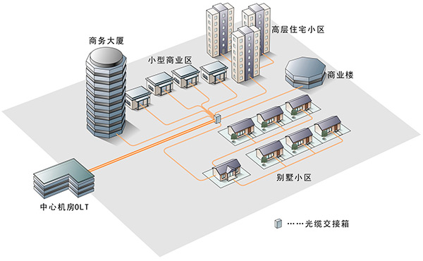
- Fixed Network Access Solution
- Hotspot Signal Coverage Solution
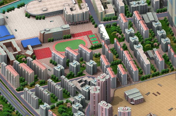
- College Campus Integrated Coverage Solution
- Large Sports (Exhibition) Venues Integrated Coverage Solution
- Railway and Highway (including tunnel) Integrated Coverage Solution
- Scenic Spot Integrated Coverage Solution
- Populated Community Integrated Coverage Solution
- Urban Metro Integrated Coverage Solution
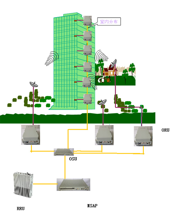
- High-rise Building Integrated Coverage Solution
- Co-construction and Sharing Integrated Coverage Solution
- Wireless Network Integrated Solution
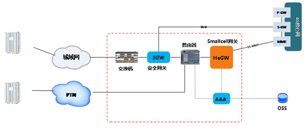
focusing transmission of different signals through one optical fiber (such as network, POTS, IPTV and WIFI) is eventually achieved
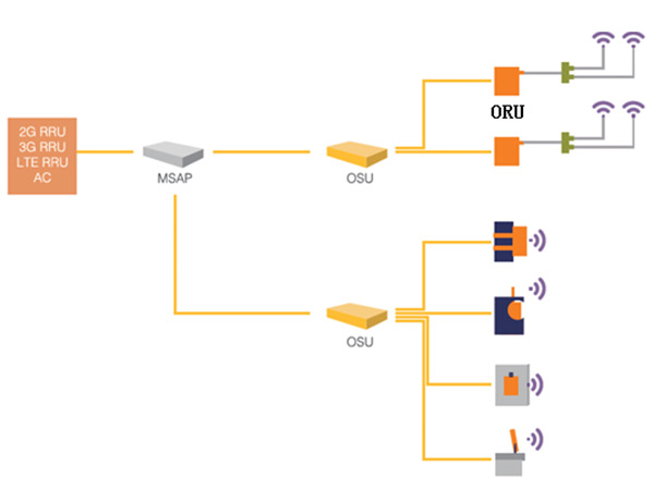
Topology:

Application scenarios: FTTH, FTTB
Plan 1: Small base station solution

Plan 2: Smartphone Companion Solution
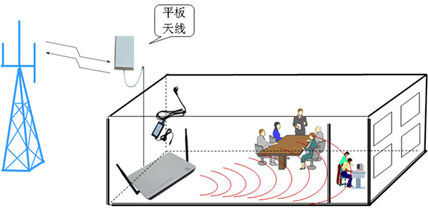
Application scenario:
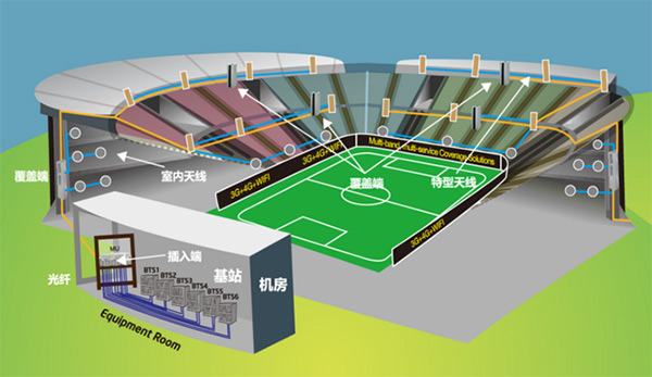
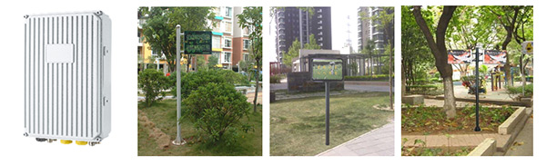
Solution: Source RRU+ optical fiber distribution system+ beautifying antenna

Plan 1: Source RRU+POI+ passive feeder system

Plan 2: Source RRU+ optical fiber distribution system
Solution: Source RRU+ optical fiber distribution system/ optical fiber repeater

Plan 1: Source RRU+ optical fiber repeater+ optical fiber distribution system+ beautifying antenna

Plan 2: Smallcell base station+ beautifying antenna
Plan 1: Source RRU+ optical fiber distribution system
Plan 2: Source RRU+ optical fiber repeater

Urban Village Scenario

Large-scale Community
Solution: Source RRU+POI+ feeder system/ leaky cable
Station hall and nearby tunnel: in long tunnel: optical fiber repeater+ leaky cable

Plan 1: Optical fiber distribution system+ wild-angle antenna

Plan 2: Source RRU+ optical fiber distribution system+ beautifying antenna
Plan 1: Source RRU+ optical fiber distribution system

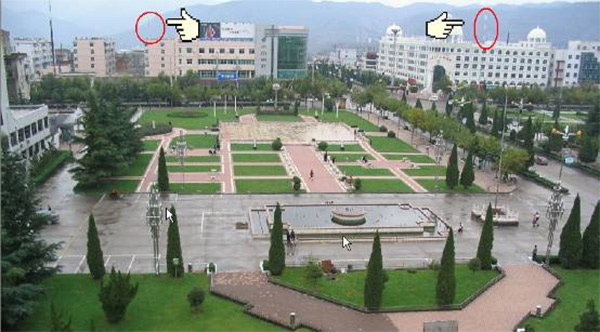
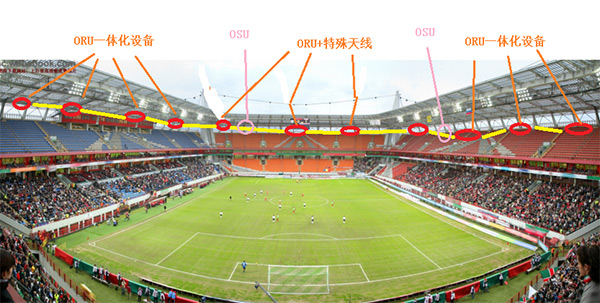
Scenario photos:
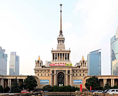
Exhibition Hall
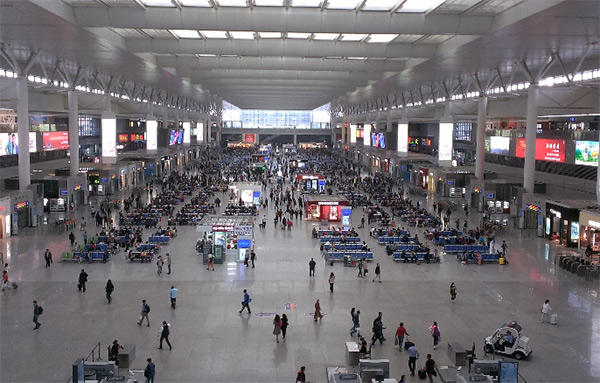
Station
Plan 2: Source RRU+ passive POI system
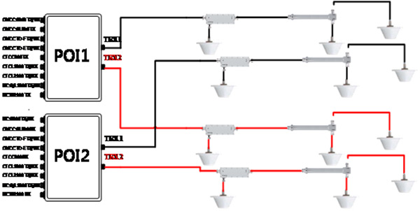
The above figure is modified as the schematic diagram according to Plan 1.
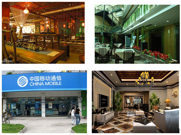
Scenario options:
Shopping mall, hotel, office building
The quality of wireless network coverage is a critical link to the business perception of mobile users. The difference of such scenarios as buildings and terrains as well as the complexity of electromagnetic environment leads to the diversity of forms of signal coverage. Based on its own technology advantages, GRENTECH develops solutions to wireless network optimization coverage in scenarios such as indoor distribution, residential community, campus, business center, large venues, airport, station, scenic spot, metro, expressway, etc.

Scenarios such as business center, large-scale residential quarter, large venues and expressway are added or emphasized in the figure above
- System Network Management Plan
- Tunnel Entrance Handover Plan
- Station Hall and Platform Handover Plan
- Underground Station Entrance Handover Plan
- Transit Tunnel Handover Plan
- Long-tunnel Coverage Plan
- Short Tunnel Coverage Plan
- Transfer Station Coverage Plan
- Station Coverage Plan
The routine operation condition of each equipment at the station is monitored and managed by the webmaster system. For system failures, an alarm can be given in time to inform relevant management personnel of this event.

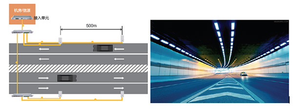
Underground tunnel coverage relies on RF signal fed by leaky coaxial cable. So, we can use the leaky cable to fees RF signal to the point near the tunnel portal, and ensure there is some residual RF signal; then, directional panel antenna is installed at the tunnel portal to extend the signals in the underground tunnel, so as to make the outdoor signal intensity stay in smooth transition; when the train runs out of the ground, the indoor signals become increasingly weakened, while the outdoor signals become increasingly enhanced; without any blackout, call drop of the mobile station due to insufficient handover time can be avoided.
The train can run at the maximum speed of 80km/h. If we calculate based on 8s as the longest handover time of GSM, then, when the covered field intensity is higher than -80dbm, we have to ensure the length of the handover section is more than 178m and well control the power of tunnel signal to ensure smooth signal handover, so as to meet the worst requirement of handover section of the running train.
Likewise, we can analyze the handover condition when the train enters the metro tunnel. Set the parameters in network and adjust the covered intensity of each tunnel to make handover smoother. See the following figure for the tunnel entrance handover diagram:

Tunnel Entrance Handover Diagram

Station Hall and Platform Handover Diagram
As a mobile user enters and goes out of the station, the position coordinate and the electrical level and field intensity of station hall signal and outdoor signal will change. See the following figure:

Underground Station Entrance Handover Diagram
With the above energy profile for reference, we analyze the worst handover condition in and out of the metro station:
Entering the metro:
The signal intensity of metro station is the same as outdoor intensity after the escalator runs for 10s and the pedestrian advances for 2s. The speed of the escalator is usually 1m/s, so the distance covered by a pedestrian entering the metro is:
8s×1m/s= 10m
At the time of design, make sure after the pedestrian enters the station hall and covers 10 m, the electrical level at the hall entrance is above -80dBm, so as to ensure that the passenger can smoothly switches between entrances. Usually, the antenna is provided at the station entrance with the covered radius of 10m, so as to ensure the handover occurs within the station.
The handover method of a pedestrian going out of the station is the same as that of his entering that station.

Transit Tunnel Handover Diagram

Long Tunnel Coverage Diagram
After the network signals of different operators pass through POI combiner, they are output to the leaky cable for signal coverage through RF coaxial cable. The train runs very fast in the metro tunnel. The application of leaky cable for signal coverage can make signals uniform enough. As or the method of signal coverage in the tunnel with coaxial leaky cable, it is to lay leaky cable on the tunnel wall inside it and achieve signal intensity coverage with the help of leakage principle of leaky cable. The distance between receiving and sending cable is ≥460mm. See the following diagram for tunnel signal coverage:

Tunnel Coverage Diagram
In order to achieve signal coverage in the carriage with the least loss, the leaky cable shall be erected at the height parallel to the metro window. Signals pass the window for the user with slight loss. The physical distance between leaky cables is increased to improve system isolation.

Transfer Station Diagram
The transfer stations along the metro line has multiple structures, and what we commonly see is a tunnel with a shared hall and different platforms. A transfer station can provide transfer by two or more lines.In the case of shared hall, the station hall can be covered by the signals of the existing line. For stations along the new line, a base station is provided in the computer room on the platform, so as to cover the tunnel and platform of the new line. The handover zone is set at the access staircase from the transfer station hall to the platform. The networking method for signal coverage is the same as that of common stations.
Two distribution systems are applied for the station, one for uplink and one for downlink. POI output connects the downlink feeder, and the downlink signals for terminal users is connected to the uplink feeder, returned to operator base station and network. See the following diagram for the station coverage:

- Smart Electric Motor Solution
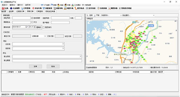
- Smart Taxi Solution
- Smart Public Transportation Solution
Monitor the vehicle position and traveling track on a real-time basis, and provide position information service; provide vehicle identification, vehicle dynamic monitoring, electronic fencing prevention, etc.; the function of virtual e-plate releases vehicle theft, traffic security, etc.

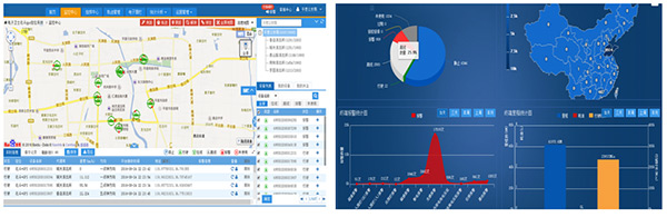
The system consists of two parts: Internet public service platform and public security organ watch platform. The public, through the Internet public service platform, can monitor the motor with the phone APP on a real-time basis and enjoy APP value-added service. The public security organ, through the watch platform, can achieve anti-theft and early warning in a precise manner, rapid response and timely treatment, so as to achieve dynamic prevention and control.
System Architecture

System Composition
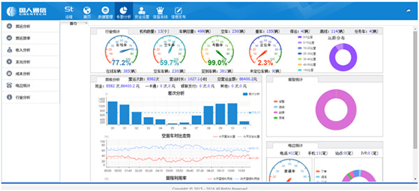
The system consists of three centers and eight business systems. Three centers include monitoring and command center, on-call service center and data resource center. Eight business systems include monitoring and command center, call service management system, enterprise online management system, dynamic monitoring and check system, service quality reputation evaluation system, integrated operation analysis system, information release management system, and all-purpose card payment management system.
Monitoring Center:

On-call Center:
Data Center:
System Architecture

System functions
With the help of vehicle monitoring and positioning technology, wireless communication and electronic map display technology, the smart public transportation system achieves real-time monitoring on route operation vehicle, motor vehicle and emergency repair vehicle, so as to improve the ability of the scheduling and command system to master the route operation status on a real-time basis and contingency ability.
With passenger flow real-time statistics technology, carry out passenger flow real-time statistics and analysis for each station, each route and each time period, so as to provide data support for vehicle scheduling by route controllers and provide timely and accurate basis for managers’ decision.
Improve personnel quality and labor productivity, optimize personnel and post structure, and reduce management cost. Achieve the best resource allocation of vehicle ratio, drivers and managers.
E-plates along the route provide citizens with timely and accurate information about vehicle arrival, and improve the service quality of urban public transportation.
Record the information data base safely, so as to provide reliable data support for accident evaluation system and prevention system.
- Smart Community Public Service Platform
- Urban Life Service Platform
- Smart Tourism Promotion Sharing Platform
Smart Community Public Service Platform puts management and service as its core concept. On one hand, it uses the available grid community service management system to create a new smart community management pattern that is comprehensive, integrated and sharing. On the other hand, it puts community residents as the core and provides convenient, efficient and safe smart services, so as to fully meet the requirement of residents in food, housing, transportation, travel, shopping, entertainment, health, and so on.

The smart community makes full use of information technology, Internet (and Mobile Internet) technology and cloud computing technology, develops, integrates and utilizes information resources, and promotes information exchange and knowledge sharing.
It is not information isolated island between communities, but an interconnected community network.
In a smart community, smart control, smart management, smart instrument, smart home and related automation technology are widely applied.
The smart community uses information technology and Internet technology, considers the advantages of local service, focuses on the requirement of owners, carries out colorful community services and value-added services. In this way, owners can stay at home and enjoy convenient people-oriented service experience.
The platform is to build a better information-based city, improve governance efficiency and integrated service level of the government, and enhance satisfaction and happiness of local residents.
Through smart city top-level design, information resource integration, governance application, urban management application, smart livelihood and the like, joint efforts are made to create a palm-based life service system. By integrating government resources and diverse life services, one-stop urban life service is realized in the mobile phone; high-quality convenience resources break through space-time limit, and common people can stay at home to enjoy convenient and efficient services. By creating an urban life service platform on which the government collects and pays fees while citizens consume and make payments, so as to provide the government with more convenient information-based management and provide citizens with more convenient digital service.
With smart city APP as the carrier, create the smart city life service platform and integrate diverse smart livelihood applications, so as to make smart city “palm-based and approachable”. Open up new business pattern, and achieve sustainable operation of the platform.
Six sections of totally 27 primary services include:
Convenience Service: social security and provident fund query, appointment register, living payment, virtual citizen card, etc.
Transportation Service: bus arrival reminder, public bike site, traffic violations query, real-time traffic status, etc.
Government Affairs Service: government information release, Mayor's Hotline, etc.
Travel Service: tourism e-commerce, smart tourist spot, periphery tourism, etc.
Information Service: news, retailers’ promotion activities, etc.
Social Service: urban problem feedback, life and traveling share, etc.
With “Travel to Famous Cities APP” as the carrier, “GRENTECH Smart Tourism Promotion Sharing Platform” provides full technical support for the activity “Travel to Famous Cities in China”. With the help of network video, beautiful pictures, literal wrapping, community interaction and other new media forms, efforts are made to improve the awareness and reputation of county tourism on the platform across China.
Through “GRENTECH Smart Tourism Promotion Sharing Platform”, county-level tourism government can carry out macro comparison on nationwide scenic sport service, so as to precisely master the preference of target tourists, have a clearer objective and direction towards future plan of the scenic spot, help improve service level of county region and scenic spot, reduce management cost and improve management efficiency.
1、Value provided by the platform to counties and cities
● 100+100+ urban tourist traffic import
● Tourism resource video wrapping and promotion
● Tourist route customization and recommendation
● Scenic spot and specialty online sales and promotion
● Multiple-channel marketing through online We Media
2、Services provide by the platform to tourists
● Recommend featured tourist destination in China
● Buy tourism-related products online
● Travel coordinate, footprint, route record, punch card
● Post photos and videos, and discover interesting details
● Interaction and sharing (launch diverse theme travels and activities)